Optical Model Product
Metadata
Data product name |
DpdSirOptModel |
Data product custodian |
SIR |
Name of the Schema file |
|
Processing function using the data product |
SIR |
Proposed for inclusion in EAS/SAS
This product is proposed for inclusion in the SAS: no
This is an internal Data Product.
Data product elements
Header |
object of type sys:genericHeader |
Data |
object of type sir:sirOptModel |
QualityFlags |
object of type dqc:sqfPlaceHolder |
Parameters |
object of type ppr:genericKeyValueParameters |
Detailed description of the data product
The sirOptModel describes the spectroscopic distortions in the FOV, it works on the SIR rotated layout where the dispersion direction is almost horizontal and the dispersion direction is the same for all detectors like depicted in the following picture
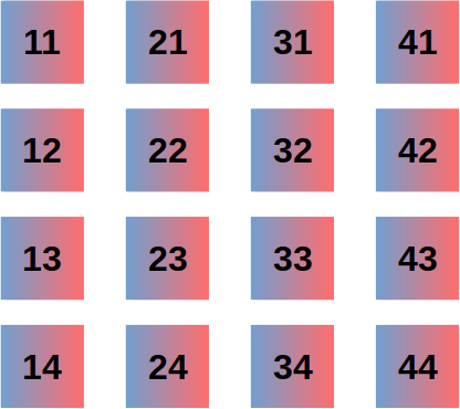
(For more details see https://euclid.roe.ac.uk/projects/sir_pf/wiki/Real_Detector_Layout)
- Data section of this model can contain 5 subsections (of type twoAxisModel):
RGS000 tilt 0,
RGS000 tilt -4,
RGS180 tilt 0,
RGS180 tilt 4,
BGS000 tilt 0;
each subsection describes the distortions of each grism.
To go from sky positions to pixel positions on the detector 4 steps are required.
Step 1: the undistorted positions
The sirOptModel uses a global WCS, which goes from sky (ra,dec) to mm in the FOV. Since objects are dispersed and no pointing sources are visible, the model goes from (ra,dec) to a reference position in the spectrum. Each spectrum order has it own reference position defined by orderAxisModel.ReferenceLambda.
The global WCS is centered on the reconstructed pointing (no on the nominal commanded pointing). This WCS provides the expected undistorted positions (\(x_{u}, y_{u}\)) positions of the objects.
Step 2: the distorted positions
The real distorted positions (\(x_{d}, y_{d}\)) are obtained correcting these undistorted positions by 2 global standard polynomials: \(\mathbb{R}^2 \rightarrow \mathbb{R}\) one to correct the \(x_{u}\) and the other to correct \(y_{u}\)
The coefficients for the 1:sup:st orders are stored in twoAxisModel.Reference The coefficients for the 0:sup:th orders are stored in twoAxisModel.Displacements (with twoAxisModel.Displacements.Order==0)
The polynomial coefficients sorting follows the same convention used by numpy.polynomial.polynomial.polyval2d
Step 3: the extra rotation correction
Due to grism wheel rotation uncertainty one extra rotation (with respect to the nominal one) could exists.
In this case the distorted reference positions must be extra rotated to obtain the final positions in mm (\(x,y\)). The center of rotation of each object changes along the FOV and each object has its own center of rotation.
The center of rotation (\(x_{p}\), y_{p}) is obtained in the same way we obtain the distorted positions and the coefficients are stored in twoAxisModel.Pivot.
This extra rotation is applied by the formula:
where \(R\) is the extra rotation matrix (2x2) defined by the extra rotation angle.
Step 4: the pixels positions
The final step is applied to obtain pixels positions on the detectors. For this steps we do not use the MDB metrology, because on real data we realized this metrology do not properly describes the instrument. We measured our own metrology and it is stored in the Parameters.SIR_DetectorsMetrology. It has the same structure of the MDB metrology file. This metrology is the same for each grism
Quality checks
The parameters section of the model contains a set of parameters named like this: RGS180_0_0th_DeltaMeas (<GWA_POS>_<GWA_TILT>_<SPEC_ORDER>_DeltaMeas)
Each keyword links to a FITS files which contains comparisons between: feature positions measured on the frame and feature positions according to the calibrated model.
Feature position are star absorption in case of 1st order calibration and 0th order peak in case of 0th order calibration.
More in details columns of these tables are:
PTG_ID: the pointing ID of the object
ID: the MER object ID
DET: the detector ID of the object
RA and DEC
XOBJ: the feature X position using an ideal WCS (no optical distortions) [mm]
YOBJ: the feature Y position using an ideal WCS (no optical distortions) [mm]
XMOD: the feature X position according to the OPT model [mm]
YMOD: the feature Y position according to the OPT model [mm]
XMEAS: the feature X position measured on the frame [mm]
YMEAS: the feature Y position measured on the frame [mm]
XABS_DELTA: the difference between X measured and X expected feature position [mm] (XMEAS-XMOD)
YABS_DELTA: the difference between Y measured and Y expected feature position [mm] (YMEAS-YMOD)
Detector Model
The DetectorModel is fundamental to describe the transformation between pixels and mm in the FOV, but it is not an official DpdProduct because this model was supposed to be stored in the MDB (see SpaceSegment.Instrument.NISP.NISPDetectorSlots keyword).
On fly SIR realized the values contained in the NISPDetectorSlots*csv (the file referenced by SpaceSegment.Instrument.NISP.NISPDetectorSlots) are not describing properly the instrument.
For this reason SIR recomputed these values and stored them in a .csv file attached to the OpticalModel as the parameter: SIR_DetectorsMetrology. This file has the same structure of the file referenced by SpaceSegment.Instrument.NISP.NISPDetectorSlots MDB parameter (see documentation of that parameter for details)
The DetectorModel works in the SIR rotated layout (as the OPT does). This model uses the WCS description contained into the .csv file and the standard wcslib to perform the conversion \(mm \longleftrightarrow pix\).